Currently many automotive applications are based on the use of fuel as a primary energy source such as batteries and super-capacitors auxiliary power source. The use of super-capacitors reduces power stress on the main power source and meet the requirements..
Currently many automotive applications are based on the use of fuel as a primary energy source such as batteries and super-capacitors auxiliary power source. The use of super-capacitors reduces power stress on the main power source and meet the requirements of wheel motors in the event of rapid energy demand since the latter it is stored and ready to be consumed directly; namely the fuel cell take a moment to also produce renewable energy, the delay is justified by the chemical reactions in the cell conversation [1].
The maximum speed is 136 km/h, with acceleration from 0 km/h to 100 km/h in 10.3 sec.
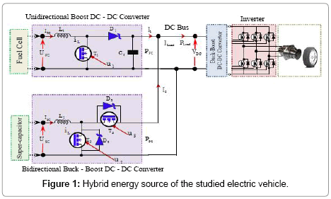
The portion of the hybrid source in our VE consists of:
1. A PEM fuel cell consists of two blocks connected in parallel. Each block has three stacks connected in series. A stack has a power of about 8 kW, it consists of 125 cells. The hydrogen feed is ensured by compressed hydrogen tanks 26 to 350 bars.
2. Battery super capacitors are composed of two blocks connected in parallel. Each block contains 141 super capacitor cells connected in series. A cell has a capacity of 1500F and a nominal voltage of approximately 2.5V. It has a maximum specific energy of 5.3 Wh/Kg and a maximum power density of 4.8 kW/kg.
3. Intermediate converter is a boost converter connected to the battery; a buck-boost converter connected to super capacitors and an inverter connected to the DC bus whose voltage should be regulated to 300V switches used are 600V IGBT with antiparallel diodes [2].
4. An asynchronous motor with a rated power wheels is in the order of 37 kW and maximum torque is 255 Nm.
In the remainder of this study is based on our EV to size the power source and power buffer storage elements and for energy management.
Sizing of hybrid energy source for EV
The objective of this section is to present a design method of power sources in a VE hybrid energy source (fuel cell/super-capacitors), i.e. determine the number of battery cells fuel and the number of supercapacitors cells [3, 4]. The electrical system studied VE shown in Figure 1 is included:
1. Two DC-DC converters which adapt the voltage levels between the two sources and the DC bus. The converter associated with the cell operates in Boost mode. It allows to raise the battery voltage to 300V. It is unidirectional. The other converter, interposed between the super-capacitors and the DC bus, is reversible. It operates in Boost mode when super-capacitors provide electrical energy to the DC bus and Buck mode in case the batch battery electric power is supplied to the supercapacitors to load [5].
2. An inverter connected to the DC bus.
3. An asynchronous motor which can drive the vehicle wheel.
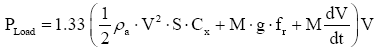
In order to dimension the power sources of the vehicle, it is important to estimate the power required by the electric vehicle. It is expressed assuming that the road is plane by [4]: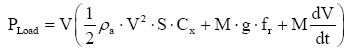 (1)
(1)
where:
M: Total vehicle weight (kg).
V: Vehicle speed in (m/s).
S: Frontal area of the vehicle (m2).
Cx : Coefficient of air penetration.
advances-in-automobile-engineering  :Density of the air mass (= 1293 kg/m3).
fr : Coefficient characterizing the rolling resistance;
g: Acceleration due to gravity (9.81 m/s2).
Modelling of electrical system R of EV
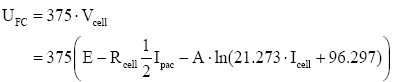
Fuel cell voltage delivered depending on the output current: By grouping all losses causing voltage drops in a PEM fuel cell, the voltage of a cell can be expressed in terms of the current by the following equation [6 - 10]: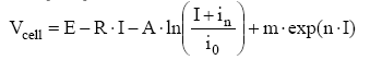 (2)
(2)
Where “E” is the reversible circuit voltage of the cell, it is about 1.2V; I is the current; R is the total specific resistance; “m and n” are two constants used in expression of the voltage drop due to concentration losses. The value of “m” is the order of 3 × 10⁻⁵ V and “n” in the range of 8 × 10⁻³ cm2 mA-1; i0: exchange current density at the cathode because the cathode overvoltage is more than that of the anode, i0 is of the order of (0.04 mA/cm2); in : internal current density equivalent to the migration of some molecules hydrogen; A: the Tafel coefficient is of the order of 0.06 V [10].
Normally the charge transfer phenomenon occurs only when exceeding a certain current value. Therefore, this phenomenon is not taken into account. Thus, the cell voltage will be expressed by the equation:
 (3)
(3)
where:
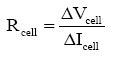
Icell : Drain Current in a cell;
Rcell : Resistance of the membrane of a cell which represents the ohmic losses; a and b: two real constants.
Rcell is simply calculated by the formula:
 (4)
(4)
ΔIcell is calculated for a current of 40A ≤ Icell≤60A , a and b were calculated by solving a system of two equations based on two different values of Icell.
Neglecting the resistance of the connections between the battery cells, the total voltage supplied by the stack is given by [7 - 9]:
 (5)
(5)
Dynamic evolution modeling of the super-capacitor: The battery of super-capacitors used in our electric vehicle is composed of two blocks connected in parallel. Each block contains 141 super-capacitors cells (the capacity of a cell is assumed to be constant whose value is to 1500F) [4]. The battery super-capacitors are represented by an electrical circuit of the RC type in Figure 1.
When:
Csc : Total capacity of the battery of super-capacitors (assumed to be equal to 21, 27F);
Rsc : Total series resistance of the battery of super-capacitors assumed to be equal to 0.066 Ω. It should be noted that the resistance of the connections between the cells is neglected.
The “ QSC ” is the amount of charge stored in the battery of supercapacitors. It is given by:
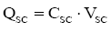 (6)
(6)
The current super-capacitors is given by:
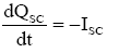 (7)
(7)
The voltage of the super-capacitors is given by:
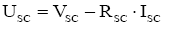 (8)
(8)
Modelling of the on-boards converters operation:
The modelling will concern only the main converters (Boost and Buck-Boost). The inverter and the asynchronous machine are simulated by the presence of a current source. This current is called a load current. This current is assumed to be known. More specifically, will be estimated from the vehicle speed are u1, u2 and u3 the control signals of the transistors T1, T2 and T3 respectively (Figure 1). A capacitance ‘Cp’ is connected in parallel to the fuel cell. In fact, this ability helps protect the fuel cell against over-voltage at a high power demand.
When the second converter (related to super-capacitors) operates in Boost mode, the behavior of both converters is described by:
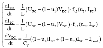 (9)
(9)
Now if the converter operates in buck mode, the behavior of both converters will be described:
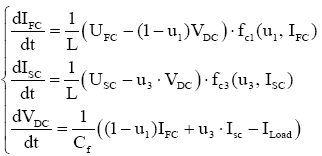 (10)
(10)
Both systems can be grouped into a single system:
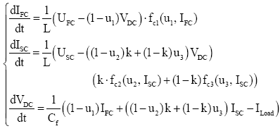 (11)
(11)
Where “k” is a binary variable that takes the value 1 when the second converter (related to super-capacitors) operates in Boost mode and 0 in Buck mode. And fc1,fc2 and fc3 functions are introduced into the system for modelling the behavior of the diodes that is D1, D2 and D3 and when the converters operate in discontinuous conduction fashion.
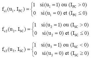
Functions: fc1 , fc2 and fc3 are defined by :
The calculation is derived from the velocity profile “V” followed by the EV. The total mass of the vehicle motioned 1680 Kg (including the mass of energy sources and converters). The total power requested by the vehicle is expressed by the equation
(1). Assuming the subsystem consists of the inverter and the induction motor operates with a yield of 75% and the DC bus voltage “ VDC” is regulated to 300V, load power is given by:
 (12)
(12)
This power is translated by a load current which is given by:
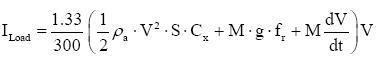 (13)
(13)
Knowing the speed of the vehicle cycle, equation (13) with the objective of estimating the load current at the DC bus in order to calculate the trajectories of current required from the vehicle power sources.
Results and Discussion :
The hybrid power source is designed for an output voltage of 300V considered to provide the inverter to meet the requirements of the EV propulsion system (wheel motors). The management of hybrid energy source in our first electric vehicle is based on the intervention of the super-capacitor battery transient regimes such as slopes, overtaking and acceleration fugitive. Second at steady state, the fuel cell alone intervenes to ensure propulsion power.
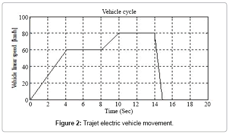
Assuming for the simulation test VE path of Figure 2. The results identified by the Figure 3 shows the response of the output voltage of the hybrid source. The power delivered by the fuel cell and the power delivered by the battery of super-capacitors the vehicle starts on a rectilinear path with a linear speed of 60 Km/h for 0-4.12 sec and 80 Km/h for 8-10 sec as a transient time when the super-capacitors ensures power supply to 300V (Figure 3) through the DC-DC Buck- Boost converters to deliver a power of 18-23 kW (Figure 4), during this period the fuel cell is not connected to the DC bus, these responses warrant the battery of super-capacitors intervene to the transitional regime.
 At 4.12-8 length and 10-14 sec, the DC-DC boost converter connected to the fuel cell works for the latter provided the necessary power for the EV power where the voltage is 300V keep (Figures 3 and 4). In this case, controlling the opening and closing of the switches is performed by a Proportional Integrator controller that calculates the state 0 or 1 of the connections of the DC-DC converters. The calculation of these statements is comparable by the PI controller when the demand for power PLoad remains constant is the steady state (state 0 for battery and one for the stack) and the opposite for the transitional arrangements (the state 1 for the battery and for the stack 0) (Figures 3 and 4).
At time 14-15 seconds, the vehicle idle for a period of one second to stop in this phase the battery super-capacitors receives power from the fuel cell for charging, this phase called the recovery phase.
Conclusion :
This work focuses on the design of critical behaviors that are considered electric vehicle battery PEM fuel type, super-capacitors and converters connected to it in our power source. In addition, presents the modeling of the behavior of energy sources and DC-DC converters associated with these sources. Simulation tests show the operation of the hybrid energy source and energy management applied to the electric vehicle.
References
- Rose R, Vincent W(2004) Fuelcellvehicle, World Survey 2003, Thèse de Doctorat, Breakthrough Technologies Instruite Washington.
- Allaoua B, Laoufi A (2011)Application of arobustfuzzysliding mode controllersynthesis on a buck-boost DC-DC converter power supply for an electric vehicle propulsion system.Journal of Electrical Engineering &Technology 6: 67-75.
- Kotz R, Bàrtschi M, Bùchi F, Gallayl R, Pli D (2002)Power of a fuel cell car boostedwitlisupercapacitors. 12th International Seminar on Double Layer Capacitors and SimilarEnergy Storage Devices, Deerfield Beach, USA, December.
- Dietrich P, Bùchi F, Tsukada A (2003)Hybridpower-A technologyplatformcombininga fuel cellsystem and a supercapacitor, Handbook of Fuel Cells.
- Allaoua B, Laoufi A (2013)A robustfuzzysliding mode controllersynthesisapplied on boost DC-DC converter power supply for electric vehicle propulsion system. International Journal of VehicularTechnology 6: 1-9.
- Maker H (2004) Modélisation d’une pile à combustible de type PEM, Thèse de doctorat, Université de Franche-Comté.
- Rajashekara K (2000) Propulsion system stratégies for fuel cellvehicles. SAE 2000 World Congress, Detroit, Micliigan.
- Chan CC (2007) The state of the art of electrichybrid and fuel cellvehicles.Proceedings of the IEEE, InvitedPaper95: 704-718.
- Candusso D (2002) Hybridation du groupe électrogène à pile à combustible pour l’alimentation d’un véhicule électrique, Thèse de Doctorat, Institut National Polytechnique De Grenoble
- Larminie J, Dicks A (2003) Fuel cell systems explained. Vol. 2. Chichester, UK: John Wiley Sons.
Brahim Mebarki is working at Laboratory of Smart Grids and Renewable Energies, Tahri Mohammed University of Bechar, Algeria. His international experience includes various programs, contributions and participation in different countries for diverse fields of study. His research interests reflect in his wide range of publications in various national and international journals
Brahim Mebarki, Laboratory of Smart Grids and Renewable Energies